Shaft Support Assembly: five parts, two unit systems, one caught conflict
A training drawing package, modeled part by part in Onshape and assembled with standard hardware. (Practice project: an original drawing set, not a client job.)

The package
Six drawing sheets: an assembly sheet (section view, top view, isometric, balloons, BOM) and five detail sheets.
- Base plate, 6061-T6 aluminum: hole table with GD&T position tolerances, blind dowel holes shown in section, edge chamfers called out only in a general note.
- Bearing bracket, 6061-T6: Ø22 H7 bore with position and parallelism controls, counterbored screw holes and dowel holes on crossed diagonals.
- Shaft, C45 steel: Ø16 g6 journal, a shoulder undercut fillet shown only in a 5:1 detail, a DIN 471 retaining-ring groove, and a tapped hole in the head.
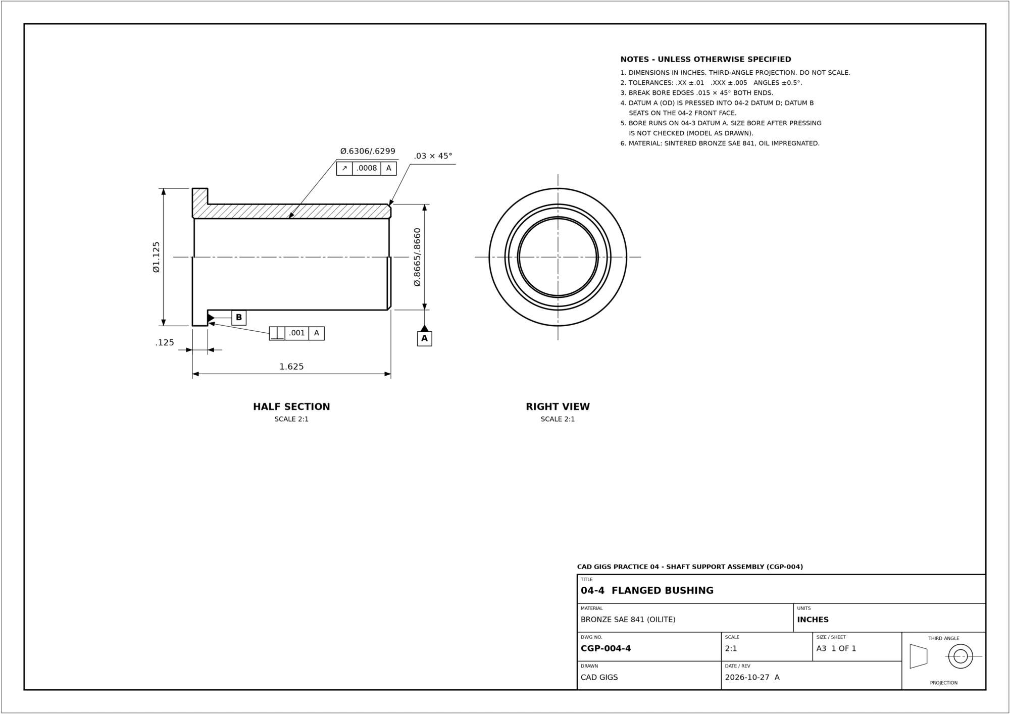
- Flanged bushing, SAE 841 bronze: drawn in inches with limit dimensions, inside a metric assembly.
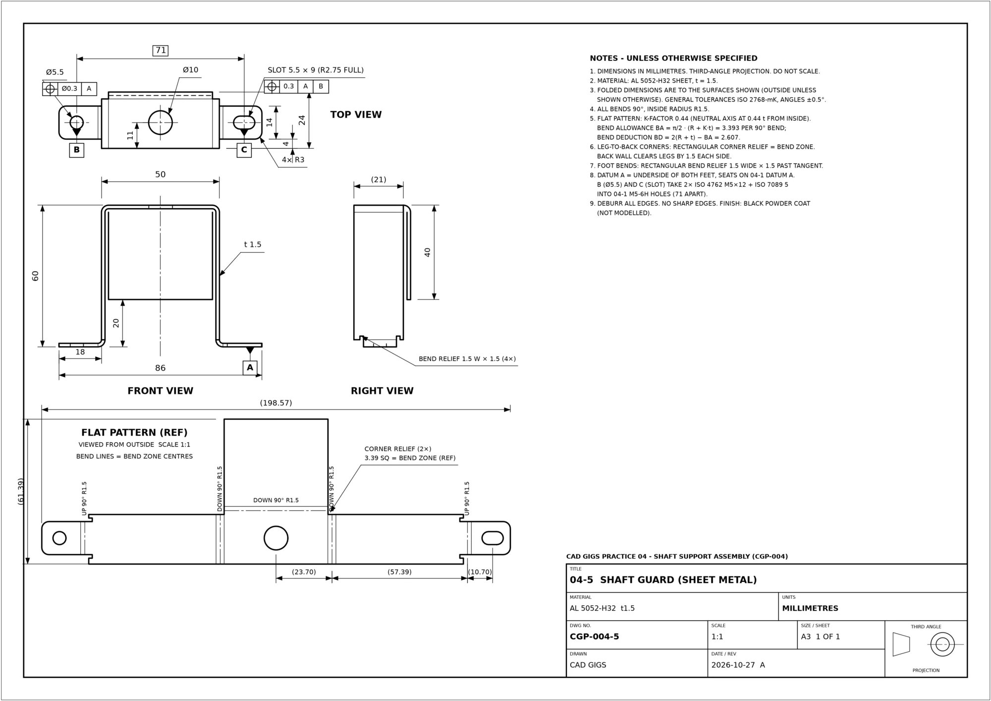
- Shaft guard, 5052-H32 sheet, 1.5 mm: a bent U-shaped guard with partial-width feet, bend reliefs, a hole and a slot on the plate's mounting pattern.
The drawing sheets
Original practice drawing package (CGP-004, Rev A). Select a sheet to open it full size.
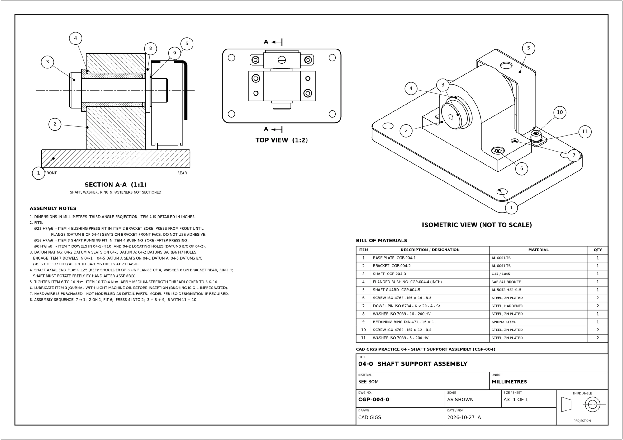
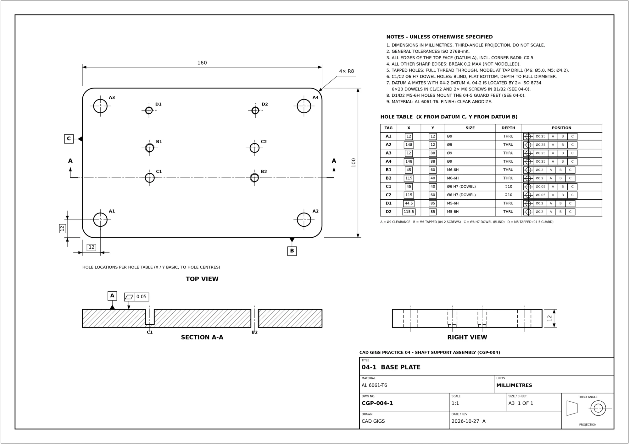
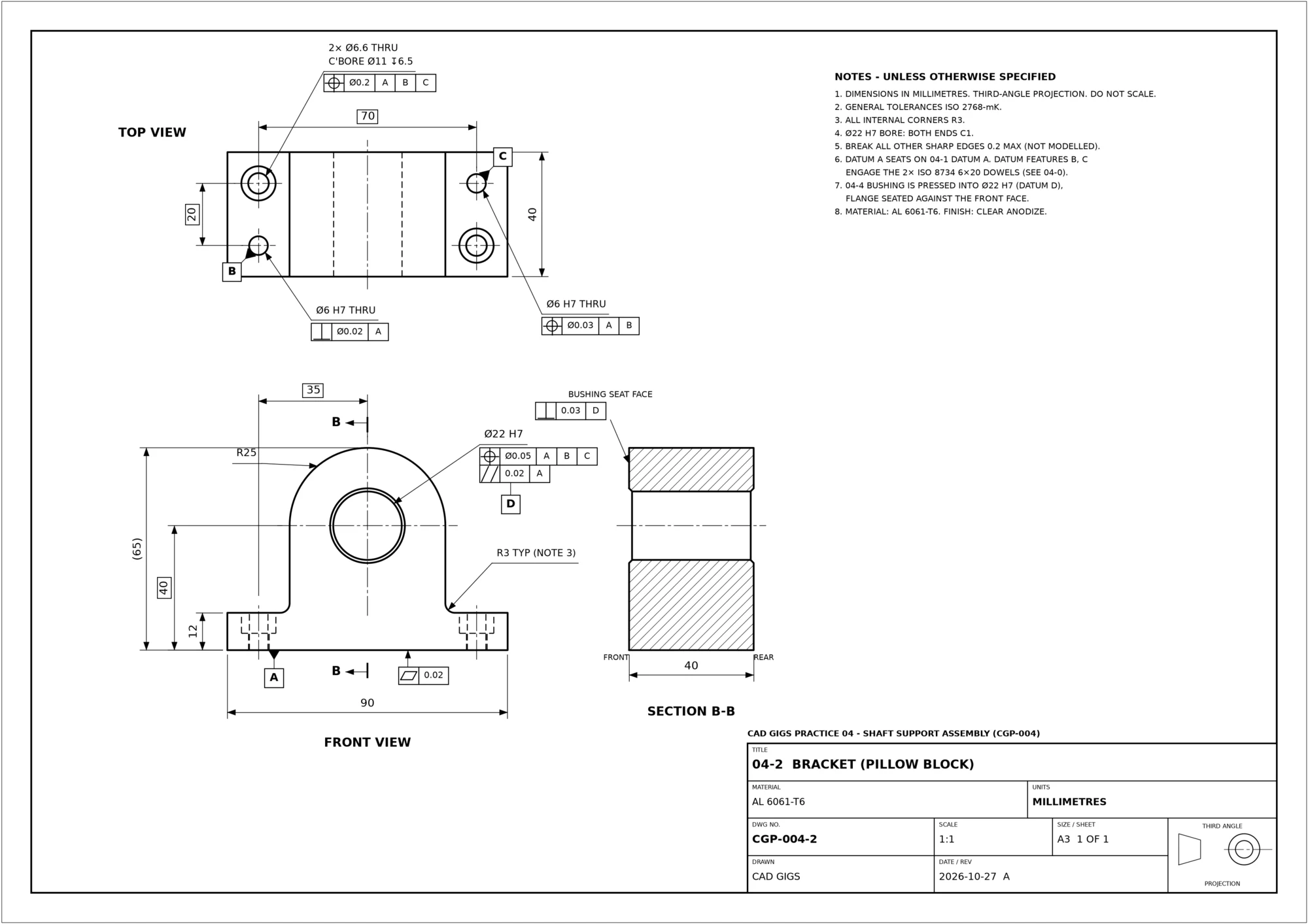
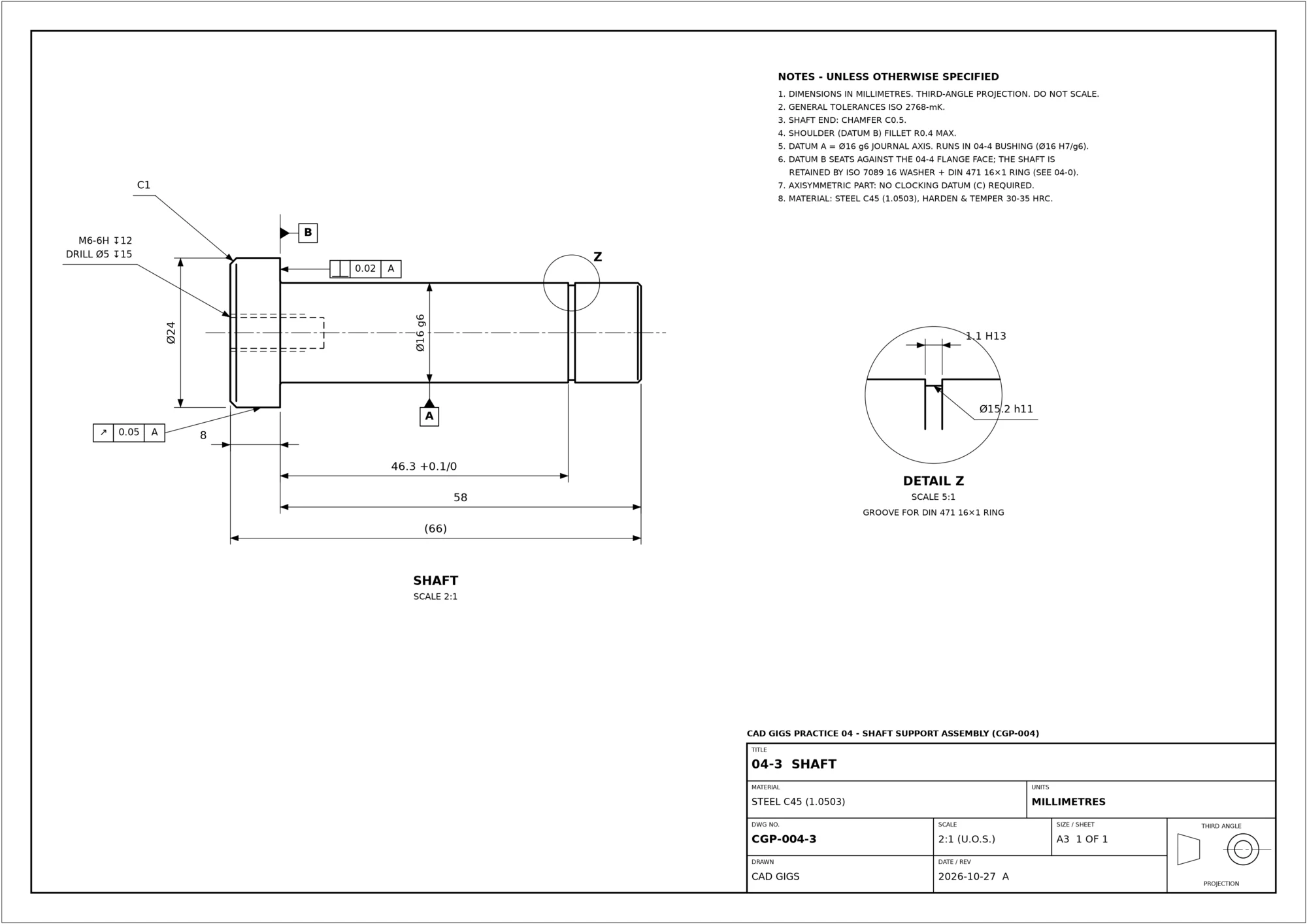
What I did
- Read every note, not just the dims. Edge breaks, the shoulder fillet, and chamfers that appear only in general notes or detail views were all modeled.
- Modeled toleranced sizes on purpose. The g6 journal is 15.983–15.994 mm, so modeling it at a flat 16.000 would put the model out of tolerance. Limit-dimensioned features were modeled at mid-limit.
- Caught a conflict before it became a part. The assembly notes call for an H7/p6 press fit between the bushing and the Ø22 bore. Converted to metric, the bushing OD on its own drawing (.8665/.8660 in = 22.009/21.996 mm) only gives a transition fit in an H7 bore; a p6 shaft would be 22.022–22.035 mm. On a real job, that goes back to the client as a question before anything is machined: which one do you want, the drawn size or the noted fit?
- Built the guard as real sheet metal. Modeled folded, not flat, with 1.5 mm thickness, 1.5 mm inside bend radius, and K-factor 0.44. Material side set so dimensions land on the outside faces as the note required. Feet are partial flanges with set offsets, corner reliefs and R3 corners, and the flat pattern was checked from Onshape's flat view.
- Checked the dimension chain before calling anything a mistake. A foot offset that looked wrong (4 mm) was correct once the chain was added up (4 + 14 + 3 = 21).
- Assembled with motion and real hardware. The shaft turns in the bushing on a revolute mate. Hardware came from Onshape standard content: ISO 4762 socket head screws (M6×16 for the bracket, M5×12 for the guard), ISO 8734 dowel pins (Ø6 m6), ISO 7089 washers, and a DIN 471 16×1 retaining ring sized to the 1.1 mm groove.
- Rendered it. Onshape Render Studio with materials from the prints: clear-anodized aluminum plate and bracket, steel shaft and hardware, bronze bushing, black powder-coated guard.
Result
Every part was checked against an independent reference model and matched (volume and geometry), and the assembly positions matched the reference layout.
Why it matters for your job: Most bad parts start as a drawing nobody questioned. I read the whole print, say what's unclear, and model what the drawing actually means.